What is parallel RLC?
What is parallel RLC?
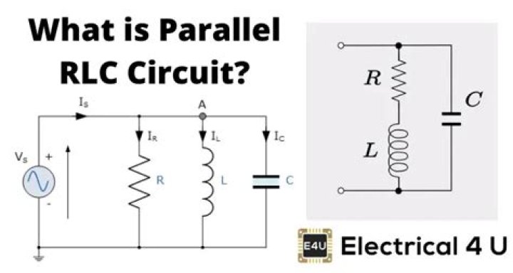
In a parallel RLC circuit containing a resistor, an inductor and a capacitor the circuit current IS is the phasor sum made up of three components, IR, IL and IC with the supply voltage common to all three. Parallel RLC networks can be analysed using vector diagrams just the same as with series RLC circuits.
What is series parallel RLC circuit?
The parallel RLC circuit is exactly opposite to the series RLC circuit. The applied voltage remains the same across all components and the supply current gets divided. In the parallel RLC circuit, all the components are connected in parallel; so the voltage across each element is same.
What is parallel RC circuit?
In a parallel R-C circuit a pure resistor having resistance in ohms and a pure capacitor of capacitance. in Farads are connected in parallel. PARALLEL R-C CIRCUIT. Voltage drops in a parallel RC circuit are the same hence the applied voltage is equal to the voltage across the resistor and voltage across the capacitor.
What does an RLC circuit do?
Radio receivers and television sets use them for tuning to select a narrow frequency range from ambient radio waves. In this role, the circuit is often referred to as a tuned circuit. An RLC circuit can be used as a band-pass filter, band-stop filter, low-pass filter or high-pass filter.
What does a resistor and capacitor in parallel do?
When resistors and capacitors are mixed together in parallel circuits (just as in series circuits), the total impedance will have a phase angle somewhere between 0° and -90°. The circuit current will have a phase angle somewhere between 0° and +90°.
Why use a parallel RC circuit?
Also, for more complex loads than the simple resistor in your circuit, if the load current varies (for example if it’s a digital logic chip with it’s outputs changing state), the parallel capacitor can provide the necessary current, which the voltage source may not be able to do because of its parasitic resistance or …