Can you use an op-amp as a comparator?
Can you use an op-amp as a comparator?
A comparator has a logic output that indicates which of the two inputs is at a higher potential. However, the best advice on using an op amp as comparator is very simple—don’t! Comparators are designed to work as open-loop systems, to drive logic circuits, and to work at high speed, even when overdriven.
What is propagation delay in the comparators of an op-amp configuration?
Propagation delay can be defined as at how much speed the amplifier responds with applied input. In the simple words, propagation delay is the delay between output and input. Propagation delay time will be valid for either positive- going a negative-going comparator outputs. Figure 2.
How a comparator circuits are used in real time industrial control applications?
The comparator circuit work by simply taking two analog input signals, comparing them and then produce the logical output high “1” or low “0“. When the analog input on non-inverting is less than the analog input on inverting input, then the comparator output will swing to the logical low.
How do you set reference voltage for comparator?
To create a voltage comparator that creates a positive voltage output if the input voltage is less than a reference voltage, apply the reference voltage to the inverting (V–) input, and the input voltage is applied to the noninverting (V+) input….Electronics Components: How to Use an Op Amp as a Voltage Comparator.
| Input Voltage | Output Voltage |
|---|---|
| Greater than reference voltage | Positive |
When op-amp is used to detect the voltage level then the circuit is called as?
window comparators
Op-amp window comparators are a type of voltage comparator circuit which uses two op- amp comparators to produce a two-state output that indicates whether or not the input voltage is within a particular range or window of values by using two reference voltages. An upper reference voltage and a lower reference voltage.
Why diodes are used in comparator using op-amp?
Many op amps have voltage clamps between the input terminals, most often implemented with back-to-back diodes (sometimes with two or more diodes in series). These diodes protect the input transistors from reverse breakdown of their base-emitter junctions.
What is the delay of comparator?
The comparator basically compares the two input signals and trips the output when one input signal exceeds the other. But the output does not change instantaneously; there is a delay as the signal makes its way (propagates) through the internal circuitry before reaching the output.
How the op-amp comparator should be chosen to get higher speed of operation?
4. How the op-amp comparator should be choosen to get higher speed of operation? Explanation: The bandwidth of the op-amp comparator must be wider so that the output of comparator can switch rapidly between saturation levels. Also, the op-amp responds instantly to any change in condition at the input.
What is an op-amp and what does it do?
What is an Operational Amplifier (Op-amp)? An operational amplifier is an integrated circuit that can amplify weak electric signals. An operational amplifier has two input pins and one output pin. Its basic role is to amplify and output the voltage difference between the two input pins.
How the op-amp comparator should be choosen to get higher speed of operation?
4. How the op-amp comparator should be choosen to get higher speed of operation? Explanation: The bandwidth of the op-amp comparator must be wider so that the output of comparator can switch rapidly between saturation levels.
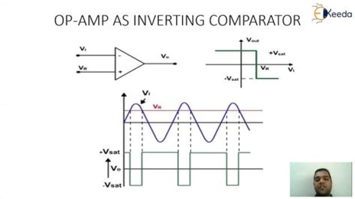
How is op-amp 741 used as a comparator?
An inverting 741 IC op-amp comparator circuit is shown in the figure below. It is called a inverting comparator circuit as the sinusoidal input signal Vin is applied to the inverting terminal. The fixed reference voltage Vref is give to the non-inverting terminal (+) of the op-amp.
What is op-amp comparator circuit?
Op-amp window comparators are a type of voltage comparator circuit which uses two op- amp comparators to produce a two-state output that indicates whether or not the input voltage is within a particular range or window of values by using two reference voltages. An upper reference voltage and a lower reference voltage.